Turbosmart BOOST CONTROLLERS – ELECTRONIC - e-Boost STREET 30 Manuel d'utilisateur

Naviguer en ligne ou télécharger Manuel d'utilisateur pour Pour la voiture Turbosmart BOOST CONTROLLERS – ELECTRONIC - e-Boost STREET 30. Turbosmart BOOST CONTROLLERS – ELECTRONIC - e-Boost STREET 30psi Manual User Manual Manuel d'utilisatio

  • Télécharger
  • Ajouter à mon manuel
  • Imprimer
  • Page
    / 9
  • Table des matières
  • DEPANNAGE
  • MARQUE LIVRES
  • Noté. / 5. Basé sur avis des utilisateurs
Vue de la page 0
1
------------------------------------------------------------------------------------------------------------------------
BEFORE YOU START – IMPORTANT NOTES
Turbosmart recommends that your E-Boost Street is fitted by an appropriately qualified technician.
Consult your local tuning specialist before setting your boost pressure as setting boost beyond your engines capability can result in
severe engine damage or failure
Turbosmart recommends that the engines Air/Fuel ratio is checked once the desired boost pressure is set. Any increase in boost
pressure can cause the engine to run lean resulting in severe engine damage or failure
Turbosmart recommends that the E-Boost Street is not used in conjunction with any type of “Draw Through” induction System.
Turbosmart recommends that boost pressure is set using a Dynamometer and not on public roads.
The E-Boost Street may not be able to completely compensate for a drop in boost pressure at high RPM due to the turbocharger
operating beyond its maximum efficiency range i.e. incorrect turbocharger sizing or excessive exhaust backpressure.
The E-Boost Street cannot compensate for increases in boost pressure at high RPM due to inadequate waste gate flow capacity;
the turbo system must maintain a steady base boost curve before you start using a boost controller.
The E-Boost Street cannot be used with external waste gates that are in a poor, worn or non-serviceable condition.
For best results your turbocharger should be correctly sized for your application.
Erratic operation of electronic parts can be caused by Electro Magnetic Interference (EMI). EMI can be generated by aftermarket
ignition systems such as CDI which, if wired incorrectly, generate large amounts of EMI through the vehicles electrical system. This
can cause items such as ECU’s and boost controllers to be effected. Please follow ignition system installation instructions VERY
carefully to avoid EMI affecting the E-Boost Street. Sometimes, using resistor type spark plugs can reduce this problem.
The E-Boost Street is not waterproof and must be mounted inside the cabin. The unit has an operating temperature range of -5
O
C
to 70
O
C.
INSTALLATION
Wiring
Red Wire – +12 Volts switched through ignition – connect via 5 Amp fuse supplied
Black Wire – Chassis, earth or ground
Yellow Wire – To 3.5V – 12V Square wave (RPM) Signal
Green Wire – External set point switching or auto dimming trigger wire (Ground to activate)
Brown and grey wire to boost control solenoid (Polarity not important)
Vacuum/pressure signal
Route the supplied hose through the engine bay and connect it to a pressure/vacuum signal from the inlet manifold.
Solenoid mounting
The control solenoid is rated to a maximum temperature of 100 degrees Celsius (212 degrees Fahrenheit), ensure that it is
mounted a minimum of 250mm (10 Inches) away from the heat of the turbo or exhaust manifold, otherwise heat shielding is
required.
Mount the E-Boost Street solenoid in an appropriate position in the engine bay with the mounting kit supplied.
Document Type: Instruction Manual
Product Name: E-Boost Street 30psi
Product Description: Electronic boost controller
Product Number: TS-0302-1001
Unit Layout
Vue de la page 0
1 2 3 4 5 6 7 8 9

Résumé du contenu

Page 1 - INSTALLATION

1 ------------------------------------------------------------------------------------------------------------------------ BEFORE YOU START – IMPOR

Page 2

2 CONTENTS FUNCTIONALITY ...2 OFF mode

Page 3

3 Changing between 2 boost groups SETUP MENU To enter the setup menu, press and hold the knob for 3 seconds. To navigate through the se

Page 4

4 SCALE (SCL) The E-Boost Street readout can be configured in either Bar, PSI or KPa, the default setting is in psi. This allows you to tailor th

Page 5

5 RPM DISPLAY CONFIGURATION (CYL) If you have connected the yellow RPM wire to an RPM signal from your ECU or negative terminal of an ignitio

Page 6 - FACTORY RESET (RES)

6 To reduce or eliminate this boost drop off, you need to input the following values: RP1 = 050 (5000 RPM) RP2 = 070 (7000 RPM) FAC = 100 - [(10 ÷

Page 7 - SOLENOID HOOK UP METHODS

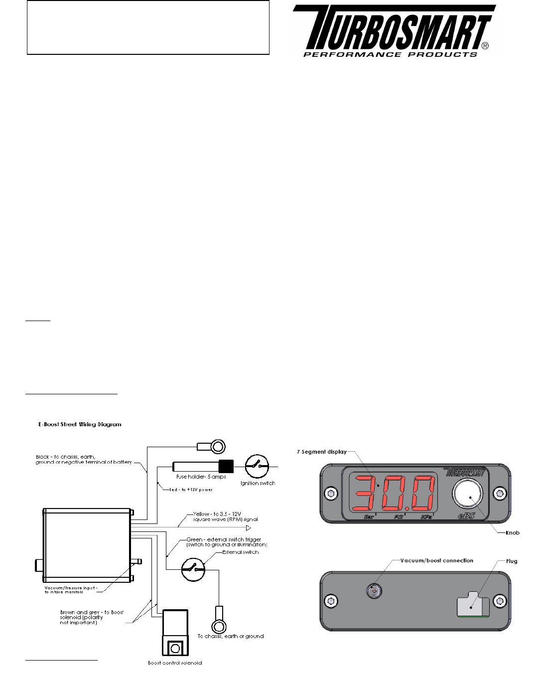
7 SOLENOID HOOK UP METHODS WARNING! Changing to different connection method can cause a higher than expected increase in boost pressure. Turbosmart

Page 8 - TROUBLESHOOTING

8 External wastegate connection methods Single port connection Method  Port 1 of solenoid vent to atmosphere  Port 2 of solenoid to

Page 9 - Happy motoring!

9 DO NOT USE ANY TURBOSMART PRODUCT UNTIL YOU HAVE CAREFULLY READ AND UNDERSTOOD THE FOLLOWING AGREEMENT. Please call if you have any questio

Commentaires sur ces manuels

Pas de commentaire